
At Fuji Electric we develop products that maximize energy efficiency and lead to a responsible and sustainable society
Industrial Inverters
Introduction
UPS or the Uninterruptible Power Supplies are used today extensively in any business to ensure uninterrupted power to critical equipment even when there are power outages or disturbances in the utility power supply. UPS use a set of batteries along with an inverter to supply power when the main utility power is no longer available. There are a variety of end-user UPS applications, each with a specific price and performance demand. While the most common form of UPS used in high power or 3 phase applications is an Online UPS, today many applications can be supported effectively with a three phase Offline UPS. On-line UPS have two power stages, a rectifier to convert AC to DC power and an inverter to convert the DC to clean AC power. An Offline UPS is inherently more energy efficient than an Online UPS because the inverter is switched off most of the time and carries the full power only when a mains power interruption is detected. State of the art Offline UPS can switch from main power to inverter/battery power and vice versa with a transfer time of only a few milliseconds (typically up to 5 ms).
Reference standards
There are many global, standards which defines the tolerance level of different type of equipment to voltage fluctuations and also to power interruptions. There are also standards, which specify the need for an alternate power source in the event of power outages. Some of the key standards are discussed below.
Interpretation of IEC standards
IEC Standards
The Intent of IEC Standard is to Define Voltage Dip Test Levels, not for Specific Types of Equipment, but attempts to define the Environment of the Equipment
- IEC 61000-4-34 applies to Equipment over 16A and
- IEC 61000-4-11 for Equipment Under 16A
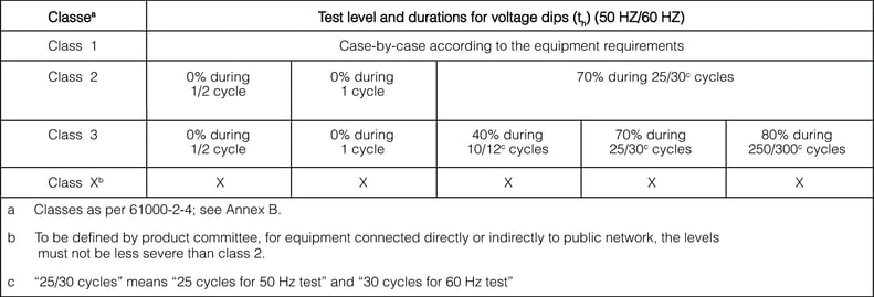
Class 1: This class applies to protected supplies and has compatibility levels lower than public network levels. It relates to the use of equipment very sensitive to disturbances in the power supply for instance the instrumentation of technological laboratories, some automation and protection equipment, some computers, etc.
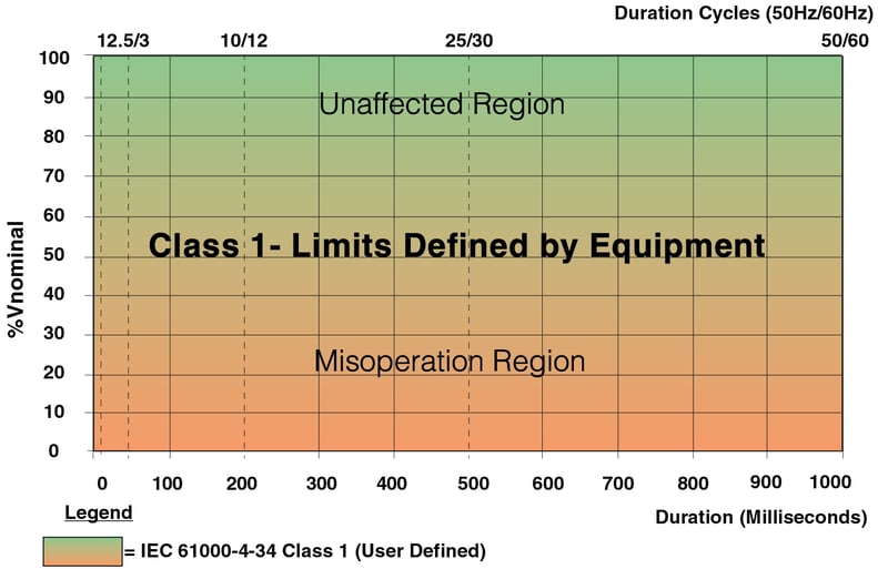
Figure 1 Compatibility Levels class 1
Class 2: This class applies to points of common coupling (PCC’s for consumer systems) and points of common coupling in the industrial environment in general. The compatibility levels in this class are identical to those of public networks; therefore, components designed for application in public networks may be used in this class of industrial environment.
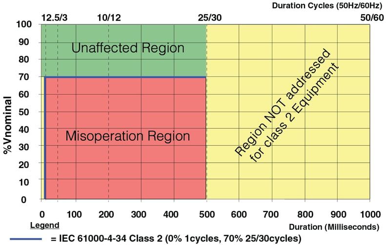
Figure 2 Compatibility Levels class 2
Class 3: This class applies only to equipment used in industrial environments. It has higher compatibility levels than those of class 2 for some disturbance phenomena. For instance, this class should be considered
i. a major part of the load is fed through converters;
ii. welding machines are present;
iii. large motors are frequently started;
iv. loads vary rapidly
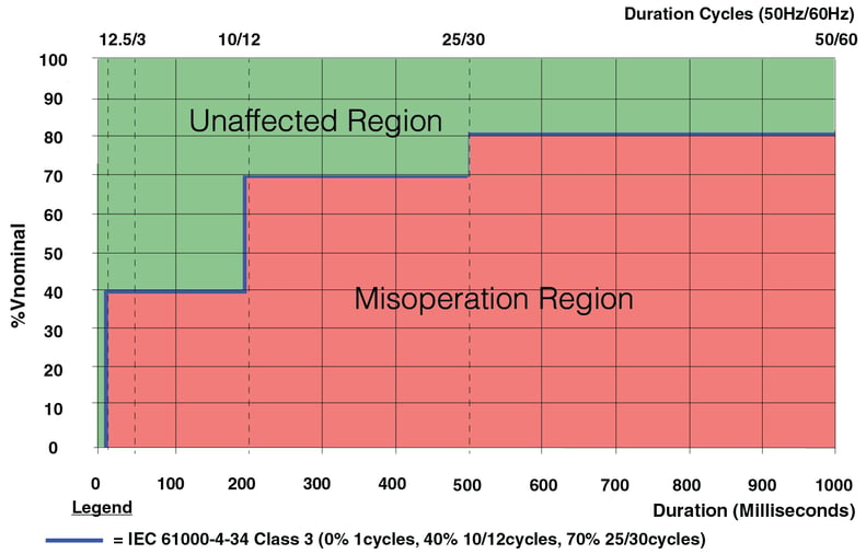
Figure 3 Compatibility Levels class 3
ITI Cbema curve
In 1977 the Computer and Business Equipment Manufacturers Association’s (CBEMA) developed a standard to address the voltage tolerance performance profile for computer equipment. Throughout the last thirty years the CBEMA Curve grew from a simple curve describing the performance mainframe computer equipment (PCs were not available), to a curve that was used to attempt to define everything from specification criteria for electronic equipment to the basis of power quality performance contracts between electric utilities and large industrial customers.
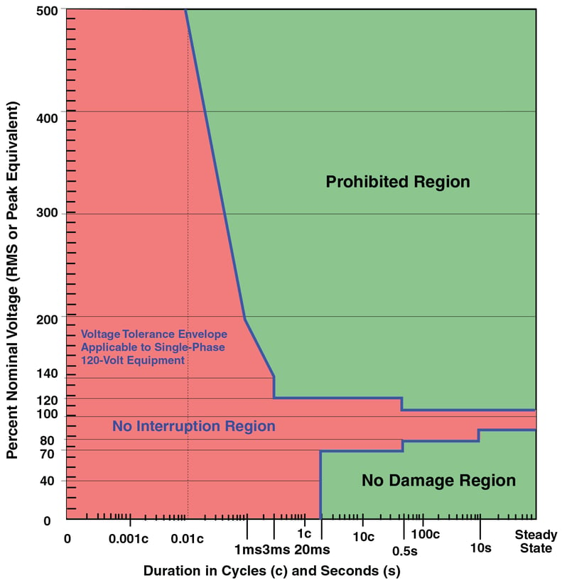
The CBEMA curve (figure 4) is a susceptibility profile with the abscissa (horizontal axis) representing the duration of the power event, while the ordinate (vertical axis) indicates the percent of voltage applied to the power circuit. In the centre of the plot is the so called acceptable area. Voltage values above the envelope are supposed to cause malfunctions such as insulation failure, over excitation and overvoltage trip. On the other hand, voltages below the envelope are assumed to cause the load to drop out due to lack of energy. In other words, the concept is that if the supply voltage stays within the acceptable power area then the sensitive equipment will operate well. However, if such an event persist for a longer time, then the sensitive equipment might fail.
National lighting code 2010,SP 72
Chapter 12, emergency lighting
Emergency lighting denotes the quantity of lighting to ensure adequate visibility in a time of emergency. In the case of power failure the illumination required to light up the escape routes will fall under the scope of emergency lighting. Evidently, such an emergency lighting shall be available for a minimum continuous period to tide over the panic situation and enable the evacuation of the building to take place. So the emergency escape lighting in all places of work and premises open to the public falls under the scope of emergency lighting.
Categories of emergency lighting
There are various reasons why special lighting facilities (defined here as emergency lighting) may have to be installed in certain buildings in the event of a failure of the supply to the normal lighting.
Three categories of emergency lighting can be identified, according to the purpose for which each is designed
Escape lighting
Escape lighting is necessary in most types of buildings in order to enable the occupants to leave the interior safely in the event of an emergency.
Escape route illumination: The horizontal illuminance (E) at floor level on the centre line of any escape route must at no point be less than 0.2 lux in order to enable occupants to avoid bumping into obstructions. However, the higher the illuminance the more likely it is that the occupants will move swiftly and confidently along the escape route so that in many cases a minimum of 1 lux may be regarded as preferable. For safe movement a uniformity ratio Emax/Emin = 40: 1 along the centre line should not be exceeded.
The escape route illumination should come on within 15 seconds after failure of the normal supply. Local
regulations may require a shorter delay time.
Safety lighting: Safety lighting is necessary in those situations where the failure of the normal lighting could place people in danger. The danger may relate to the operator, as in the use of a circular saw or the handling of hot metal, or to others, as in an operating theatre. Note that in order to prevent panic and enable help to be summoned, safety lighting should always be provided in lifts (elevators). Generally speaking, an escape lighting installation is necessary in addition to the safety lighting.
Safety lighting should be supplied within 0.5 seconds of the failure of the normal supply.
Standby lighting :Standby lighting is provided in buildings where it is decided that, for reasons other than safety, work or activities should be continued in the event of failure of the normal lighting. (Examples are shops and certain industrial activities)
Note that escape and safety lighting are enforced by law in some countries. Standby lighting, on the other hand, is not generally covered by official regulations.
The interruption time in switching from normal to standby lighting is a matter of economic consideration. In general, it should not exceed 15 seconds, although shorter interruption times may be desirable, for instance, 1.5 seconds in commercial applications to prevent shoplifting.
For all categories of emergency lighting, today in industrial and commercial establishments, UPS are used to provide the stand-by power supply system in the event of a mains failure.
Power supply systems for emergency lighting: Emergency lighting is provided for use when the supply to the normal lighting fails and must, therefore, be powered by a source independent from that of the normal lighting.
Choice of operating mode
For most types of building either a maintained or a non-maintained system will normally prove to be equally satisfactory. However, a maintained system should invariably be employed in buildings where the normal lighting can be dimmed or reduced below the levels required for escape route identification and illumination whilst the building is occupied, for example, most places of public entertainment.
Period of operation: The power supply system for emergency lighting should be designed to supply the required load for the desired period of operation. The period of operation considered desirable will
depend on a number of factors, such as the category of the emergency lighting being powered, the scale and structure of the building and the nature of the activities being carried out in it. No recommendations are made on this point, but it might be useful to note that, for many applications, it is considered that a period within the range 1 hour to 3 hours should be satisfactory. This item will, in many cases, be covered by legislation.
Maintenance: A regular schedule of testing and maintenance of all components should be established. This should include a check on the provision of the required illuminance during the stipulated period. Further details are available in Part 13 of the National Lighting code. The most cost effective power supply system for emergency lighting applications is an Offline UPS.
Working principle of Offline UPS
Offline UPS are classified as VFD topology as per IEC 62040-3.Under Normal Conditions, the loads are powered directly by the mains raw power supply(as shown in figure 5) and the Battery charger will ensure that the battery is fully charged and has it power to discharge when the power fails.
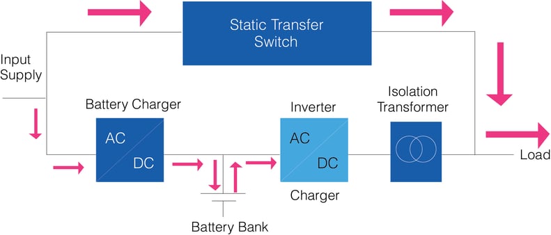
Under normal conditions, when the mains raw power is available and is heathy, the UPS continues to operate in bypass mode and when the mains raw power fails and the quality of the power is bad which are not acceptable by the loads, the operating mode changes from eco mode to online double conversion mode or battery mode.
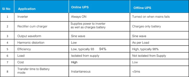
Typically the transfer has to be faster(<5ms) so that the loads cannot see the difference in the power availability. The advantages of using Offline UPS is the efficiency, typically the efficiency is around 98-99%
Working principle of Offline UPS
Applications for Offline UPS
Offline UPS Systems are used in applications where a continuous power supply is the only requirement and quality of power will not have any impact on the performance of the loads.
The Offline UPS System can also be used for applications like computers, servers etc.. But predominantly Online UPS are used when the equipment are sensitive to minor voltage fluctuations and other power quality issues faced.
Offline UPS are best suited for application where the loads meet the requirement of Class 2 & Class 3 of IEC 61000-4-11.
Some of the main applications where an offline UPS can be used to provide a cost effective and energy efficient power backup solution are
- Centrifugal fans and pumps
- Mixers
- Extruders
- Test stands
- Conveyors
- Emergency Lighting System
- Lifts/Escalators
Applications – Offline UPS System in data centres
One of the major challenges faced by the data centre managers is to reduce the energy consumption and to improve the performance of the data centre. Tightly packed server racks are generating exponentially more computer power and most of this is converted into rejected heat. The heat generated by these servers are dissipated by using Precision Air conditioner units(PAC) or using fans, chilled water pumps, and chillers. Generally, these air handling units are not connected to UPS power and they purely depend on the mains power supply for their operation or on their backup power source (generally the generator).
Typically, when the power fails, the generator takes at least a minute to come online. During which the air conditioner system is not working and unfortunately this duration is sufficient for a rapid change in the temperature of servers which could eventually result in server failure and malfunctions.
For example, When a 13kW loaded IT cabinet loses all cooling supply the ambient temperature rises from 22°C to 35°C in under 20s (0.65°K/s)
It is interesting to note the specified rate-of-change-of-temperature limit in TIA-942 = 5°K/hour (0.0014°K/s)
Applications – Emergency services
The common practice to overcome this challenge is to ensure the continuity of power by using an Online UPS system for the pumps and the fans. The main disadvantage of using an online UPS is the efficiency which is around 93~94%.
An ideal choice to ensure the continuity of power supply without compromising the efficiency is to use an Offline UPS System which guarantees an efficiency of 98% and power transfer to battery mode within 5ms which ensures uninterrupted operations of fans and pumps connected to the Offline UPS.
Applications – Emergency services
The National Building code of India, covers the requirement of emergency lightning under Volume 1, Part4-Fire & Life safety and Part 8, Building Services, Section 2 Electrical and allied installations makes it necessary in most types of buildings in order to enable the occupants to leave the interior safely in the event of an emergency. The illumination of Fire/Emergency Exit Route/Signage has to resume within 5 seconds from the failure of normal power and has to be available for a minimum of 90 minutes duration.
Also, IEC 06364-7-710,the standards for Requirements for special installations or locations – Medical locations, which states that in the event of a voltage failure of one or more line conductors at the distribution board, a special safety power supply source shall maintain luminaires of operating theatre tables and other essential luminaires, e.g. endoscopes, for a minimum period of 3 h. It shall restore the supply within a changeover period not exceeding 0.5 seconds.
The common practice to overcome this challenge is to ensure the continuity of power by using an Online UPS system for emergency lighting systems, lifts etc… The main disadvantage of using an online UPS is the efficiency which is around 93~94%.
An ideal choice to ensure the continuity of power supply without compromising the efficiency is to use an Offline UPS System which guarantees an efficiency of 98% and power transfer to battery mode within 5ms.
Applications – Offline UPS System in industrial process
Applications such as extruders, injection moulding, packaging, bottling, fibre yarns, non-woven fabric, cable manufacturing and many others requires only a continuous power supply and these loads generally falls under Class 3 of IEC 61000-4-11 and is capable to handle a power outage for 20ms.
The common practice is to use on online Double conversion UPS. The main disadvantage of using an online UPS is the efficiency which is around 93~94%.
An ideal choice to ensure the continuity of power supply without compromising the efficiency is to use an Offline UPS System which guarantees an efficiency of 98% and power transfer to battery mode within 5ms.
Industrial Inverters
- Introduction
- Reference standards
- Interpretation of IEC standards
- IEC Standards
- ITI Cbema curve
- National lighting code 2010
- SP 72
- Escape lighting
- Choice of operating mode
- Working principle of Offline UPS
- Applications for Offline UPS
- Applications – Offline UPS System in data centres
- Applications – Emergency services
- Applications – Offline UPS System in industrial process
 China
China Europe
 France
 Hong Kong
 Indonesia
 Japan
Japan Singapore
 Thailand
 USA
USA