
At Fuji Electric we develop products that maximize energy efficiency and lead to a responsible and sustainable society
UPS system configurations
Uninterruptible Power Supplies have been an important element in critical power protection schemes. Over time many different system configurations have been developed to mitigate the risk of loss of utility power. The following is a presentation of four typical UPS configurations used in industrial and commercial applications and an evaluation of each of their capabilities.
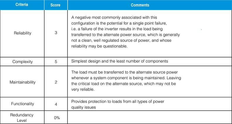
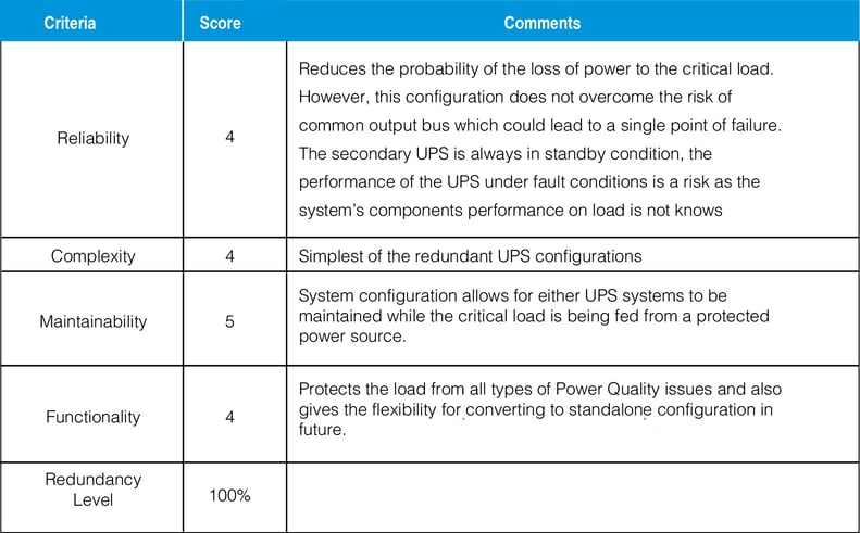
A score between 1 and 5 has been assigned. A score of “5” indicates the highest degree of criteria capability, while a score of “1” indicates the lowest degree of criteria capability
Evaluation criteria:
1. Reliability – Evaluates a configuration’s capability to maintain conditioned power to the load .
2. Complexity – Looks at the complexity of the configuration and the potential for single point failures.
3. Maintainability – The system configuration must allow for concurrent maintenance of all power system components – supporting the load with part of the UPS system while other parts are being serviced.
4. Functionality – The system configuration must be able to protect the critical load from a full range of power disturbances without transferring the critical load to external power sources, i.e. batteries or alternate power sources.
Single unit or standalone configuration
The standalone configuration (Figure 1), is the most common configuration utilized in UPS applications because it contains fewest number of major components. This system utilizes AC power (typically utility power) and converts it to DC through the rectifier. The regulated DC power is supplied to both bank of
batteries and to the inverter.
The inverter “inverts” the DC back into regulated, noise-free AC power and passes it along to the static switch. The static switch, under normal conditions, passes this AC power to the load. If a failure in the inverter should occur, or a fault on the load should occur which overloads the inverter beyond its maximum capacity, the static switch will automatically transfer to the alternate (or bypass) position and feed the critical load from the alternate power source through the static bypass switch. The manual bypass switch is a mechanical, make-before-break switch is used to bypass the UPS for maintenance purposes. When the AC power to the rectifier is lost, the batteries automatically begin supplying the required DC power to the inverter since there is no switching involved at this point.
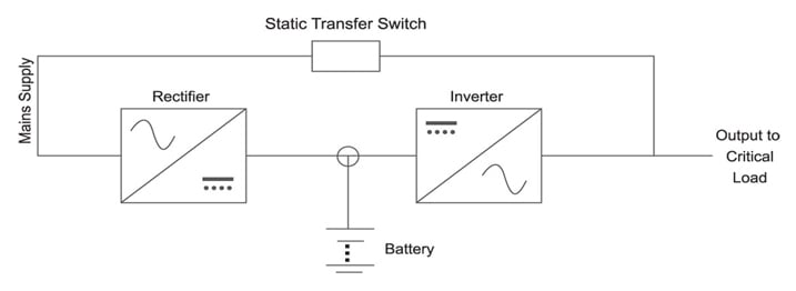
Figure 1 Standalone Configuration
Hot standby configuration
Utilizing two UPS systems (Figure 2), the hot standby configuration is the simplest form in providing a redundant configuration. In Hot standby configuration, the normal system power flow to the critical load is through UPS #1 and UPS#2 acts as standby UPS.
If UPS #1 should fail, or if the load current exceeds the UPS’s full load rating, the static switch will transfer the critical load to the static bypass (which is the output of UPS #2) within 4-5 milliseconds. When the UPS #1 is rectified, the loads will be transferred back to UPS#1 automatically without any interruption to the loads.
Under normal conditions, UPS #2 is idle but always on and ready to assume the critical load through the transfer of static switch (UPS #1). If UPS #2 should fail, its static switch will sense the loss of function and transfer the load to the system bypass source. The system bypass can be supplied through either a voltage conditioning (regulating) transformer or a non-regulating shielded isolation transformer a through a SCVS
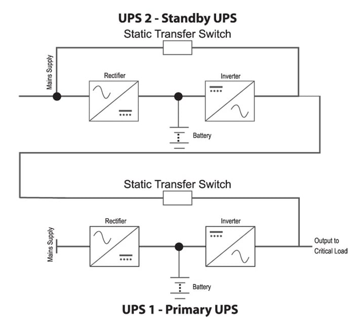
Figure 2 Hot Standby Configuration
Configuration parallel 1+1
Parallel redundant configuration (1+1)
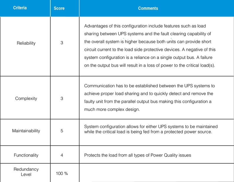
Parallel redundancy refers to the simultaneous operation of two UPS systems operating in parallel. Figure 3–Parallel Redundant Configuration, illustrates two UPS systems operating in parallel. In this scheme both UPS systems are supplying approximately 50% of the combined AC load. The failure of either UPS systems would result in the entire load being assumed by the healthy UPS. The failure of both UPS systems would result in the load being transferred to the alternate power source via the static transfer switch.
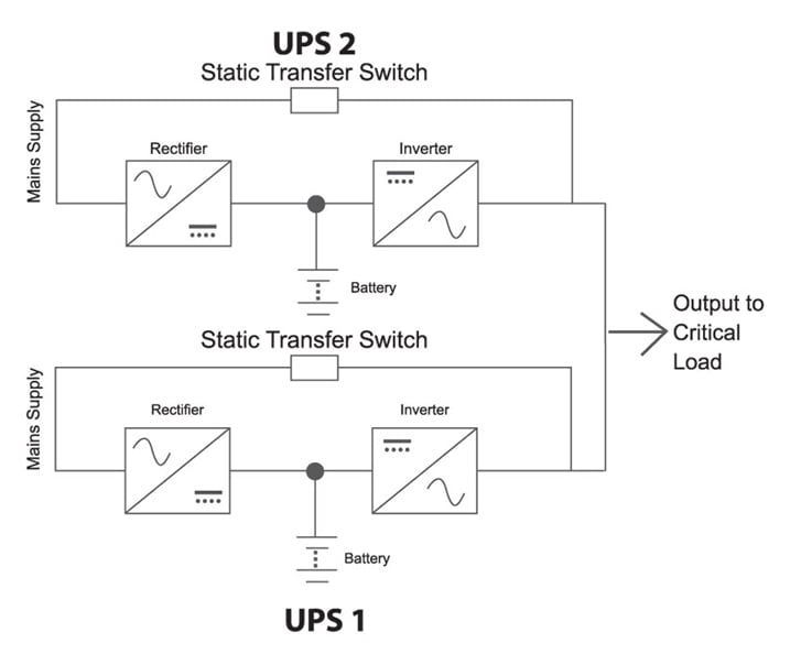
Figure 3 1+1 parallel Redundant Configuration
Parallel configuration n +1
Parallel redundant configuration (N +1)
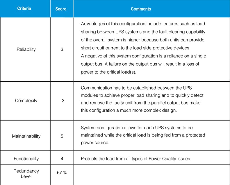
Parallel redundancy refers to the simultaneous operation of more than two UPS systems operating in parallel. Figure 4 – Parallel Redundant Configuration, illustrates three UPS systems operating in parallel. In this scheme each of the UPS systems will share equally the combined AC load. The failure of any one of the UPS system would result in the entire load being assumed by the remaining healthy UPS. The failure of two UPS systems would result in the load being transferred to the alternate power source via the static transfer switch.
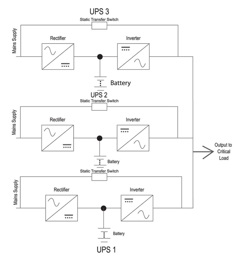
Figure 4 N+1 Paraller Configuration
Distributed redundancy
Redundancy with STS
The distributed redundant configuration, Figure 5, utilizes standalone configured UPS systems in conjunction with two stand-alone Static transfer switches. In normal operation, both units are designed to carry 50% of the critical load, and have 50% reserve capability to support the load on the other bus in the event the UPS feeding the other load bus encounters an operational problem. This allows complete independence and total isolation of the two UPS units from each other, facilitates separate output load buses, and eliminates the possibilities of single point failures either due to faults on the load side or because of faults within the two units. The result is a configuration that allows both critical load buses to be automatically fed from either the dedicated bus unit or the redundant unit.
The failure of UPS #1 would cause External Static Switch #1 to feed that system’s load from UPS #2. Similarly, the failure of UPS #2 would cause External Static Switch #2 to feed that systems load from UPS #1. Note, a common bypass feed, i.e. from the same bypass source, is necessary to ensure that the output of the two systems will be synchronized, and to allow availability of unrestricted fault clearing power.
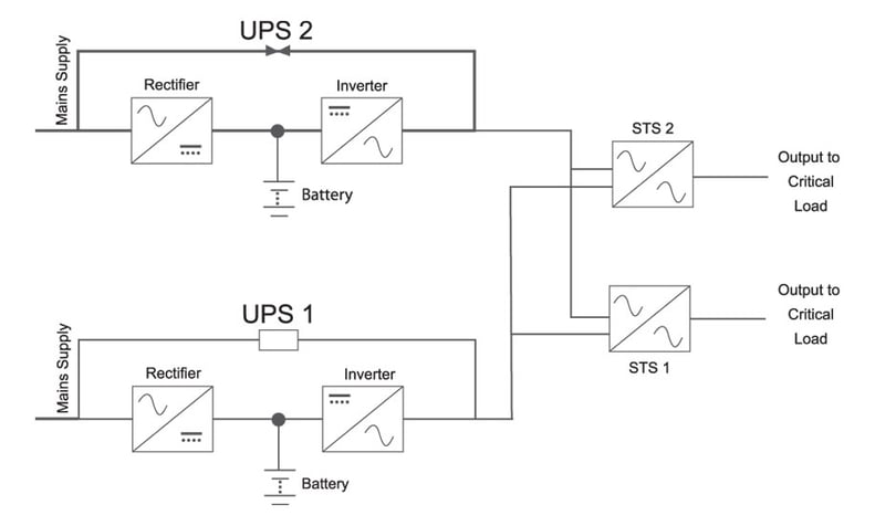
Figure 5 Redundancy with STS
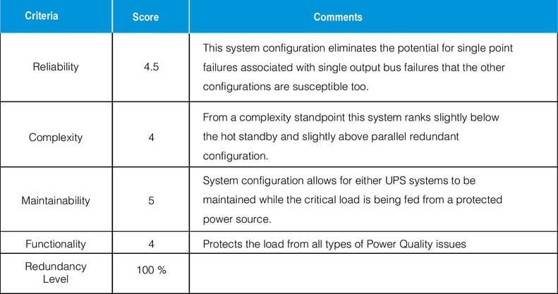
Dual bus configuration
The dual bus configuration, Figure 6 utilizes two or more UPS systems operating in parallel with two independent distribution systems. This is the most reliable, and most expensive design in the industry
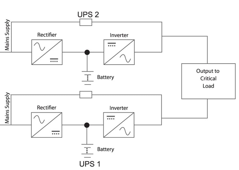
Figure 6 Dual Bus Configuration
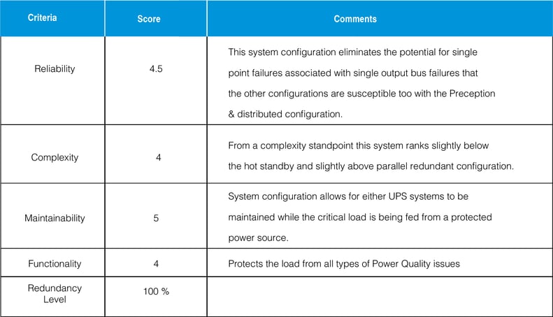
 China
China Europe
 France
 Hong Kong
 Indonesia
 Japan
Japan Singapore
 Thailand
 USA
USA